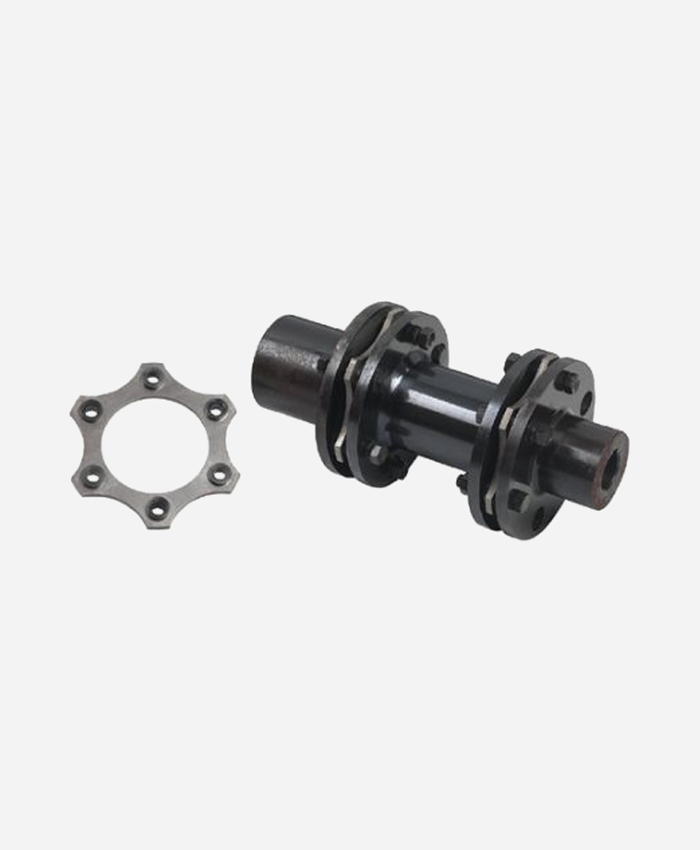
Product Description
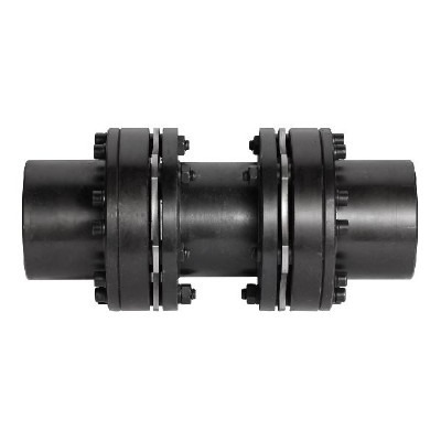
GLT-68×74 GLT Double Diaphragm Flexible Shaft Coupling For Shaft Encoder Step Motor
Description of GLT-68×74 GLT Double Diaphragm Flexible Shaft Coupling For Shaft Encoder Step Motor
>High torque rigidity, can accurately control the rotation of the shaft, can carry out high-precision control
>Designed for servo and stepping motor
>No gap between the shaft and sleeve connection, general for positive and negative rotation
>Low inertia, suitable for high speed operation
>The diaphragm is made of spring steel with excellent fatigue resistance
Catalogue of GLT-68×74 GLT Double Diaphragm Flexible Shaft Coupling For Shaft Encoder Step Motor
|
model parameter |
common bore diameter d1,d2 |
ΦD |
ΦN |
L |
LF |
d3 |
LP |
S |
tightening screw torque |
|
GLT-34×37.5 |
5,6,6.35,7,8,9,9.525,10,11,12, |
34 |
21.6 |
37.5 |
12.15 |
Φ16 |
6.8 |
3.2 |
1.5 |
|
GLT-39×48 |
6,8,9,9.525,10,11,12,12.7,14,15 |
39 |
25 |
48 |
15.15 |
Φ19 |
9.3 |
4.5 |
2.5 |
|
GLT-44×48 |
6,8,9,9.525,10,11,12,12.7,14,15,16,17,18 |
44 |
29.6 |
48 |
15.15 |
Φ22.5 |
9.3 |
4.2 |
2.5 |
|
GLT-56×61 |
10,12,12.7,14,15,16,17,18,19,20,22,24 |
56 |
38 |
61 |
19.9 |
Φ32.5 |
10.8 |
5.2 |
7 |
|
GLT-68×74 |
14,15,16,17,18,19,20,22,24,25,28,30 |
68 |
46 |
74 |
24 |
Φ38.3 |
14 |
6 |
12 |
|
GLT-82×98 |
17,18,19,20,22,24,25,28,30,32,35,38 |
82 |
56 |
98 |
30.15 |
Φ45 |
22.3 |
7.7 |
20 |
|
model parameter |
Rated torque(N.m) |
allowable eccentricity (mm) |
allowable deflection angle (°) |
allowable axial deviation (mm) |
maximum speed (rpm) |
static torsional stiffness (N.M/rad) |
weight (g) |
|
GLT-34×37.5 |
2 |
0.12 |
1.5 |
±0.18 |
10000 |
2200 |
49 |
|
GLT-39×48 |
4.5 |
0.15 |
1.5 |
±0.23 |
10000 |
4500 |
85 |
|
GLT-44×48 |
6.75 |
0.17 |
1.5 |
±0.27 |
10000 |
5500 |
107 |
|
GLT-56×61 |
20 |
0.17 |
1.5 |
±0.36 |
10000 |
11000 |
196 |
|
GLT-68×74 |
50 |
0.18 |
1.5 |
±0.4 |
9000 |
23000 |
375 |
|
GLT-82×98 |
90 |
0.18 |
1.5 |
±0.5 |
8000 |
38000 |
645 |
/* January 22, 2571 19:08:37 */!function(){function s(e,r){var a,o={};try{e&&e.split(“,”).forEach(function(e,t){e&&(a=e.match(/(.*?):(.*)$/))&&1

Proper Installation of a Diaphragm Coupling for Optimal Performance and Reliability
Proper installation of a diaphragm coupling is essential to ensure its optimal performance and reliability. Here are the steps to follow for a successful installation:
- Inspect the Coupling:
- Shaft Preparation:
- Hub Alignment:
- Tighten Fasteners Correctly:
- Check Runout and Balance:
- Lubrication (if applicable):
- Regular Maintenance:
Before installation, thoroughly inspect the diaphragm coupling for any damage, wear, or deformation. Check for proper alignment of the hubs and make sure they are clean and free from any debris or contaminants.
Ensure that the shafts to be connected are clean, smooth, and free of any burrs or rough edges that could damage the coupling or affect its performance. If necessary, use appropriate tools to deburr and polish the shaft ends.
Align the two hubs of the diaphragm coupling carefully with the shafts. Misalignment during installation can cause premature wear and failure of the coupling. Use alignment tools like dial indicators or laser alignment systems to achieve accurate shaft alignment.
Use the specified torque values and tightening sequence provided by the coupling manufacturer to tighten the fasteners securely. Over-tightening can lead to stress concentrations, while under-tightening can result in loose connections and coupling slippage.
After installation, check the runout of the coupling assembly to ensure that it rotates without wobbling or eccentricity. Also, verify that the coupling is properly balanced to prevent excessive vibrations during operation.
Some diaphragm couplings require lubrication for smooth operation. If lubrication is necessary, follow the manufacturer’s guidelines and use the recommended lubricant to prevent premature wear and reduce friction.
To ensure continued optimal performance, schedule regular inspections and maintenance for the diaphragm coupling. Check for signs of wear, misalignment, or damage, and replace the coupling if necessary. Regular maintenance can help identify potential issues early and prevent unexpected failures.
Following these installation and maintenance guidelines will help maximize the life and performance of the diaphragm coupling, ensuring reliable and efficient operation in various mechanical systems and applications.
Can Diaphragm Couplings Reduce Noise and Dampen Vibrations in Mechanical Systems?
Yes, diaphragm couplings can help reduce noise and dampen vibrations in mechanical systems. The design and material properties of diaphragm couplings contribute to their ability to minimize vibrations and noise during operation. Here’s how diaphragm couplings achieve this:
- Vibration Dampening:
- Misalignment Compensation:
- Reduced Mechanical Resonance:
- Smooth Torque Transmission:
- Compact Design:
Diaphragm couplings are designed to be flexible and allow a controlled amount of movement between the connected shafts. This flexibility helps dampen vibrations generated during the operation of rotating machinery. When vibrations occur due to load changes or misalignments, the diaphragm absorbs and dissipates these vibrations, preventing them from propagating through the system. As a result, diaphragm couplings can contribute to a smoother and quieter operation of mechanical systems.
As mentioned earlier, diaphragm couplings can accommodate axial, angular, and parallel misalignments between the connected shafts. Misalignment in rotating machinery can lead to increased vibrations and noise. By effectively compensating for misalignment, diaphragm couplings help maintain proper shaft alignment, reducing the risk of vibration-related issues and associated noise.
Mechanical resonance occurs when the natural frequency of a system matches the excitation frequency. It can lead to amplified vibrations and noise. Diaphragm couplings, with their ability to dampen vibrations, can help reduce the occurrence of mechanical resonance in rotating systems. By preventing the build-up of excessive vibrations, diaphragm couplings minimize the likelihood of resonance-related problems.
Diaphragm couplings provide smooth torque transmission between the shafts, resulting in a more uniform and stable power transfer. When torque is transmitted smoothly, there is less likelihood of sudden torque fluctuations that can cause vibrations and noise. The controlled flexibility of the diaphragm ensures that torque is transmitted efficiently, without introducing undesirable harmonics or disturbances in the system.
Diaphragm couplings have a compact and lightweight design compared to some other coupling types, such as gear couplings. This reduced mass and size help minimize inertial forces during operation, leading to lower levels of vibration and noise.
Overall, diaphragm couplings are effective in reducing noise and dampening vibrations in mechanical systems, making them suitable for applications where noise reduction and smooth operation are essential. Their ability to handle misalignments, dampen vibrations, and transmit torque accurately contributes to improved performance and reliability in various industrial settings.
How Do Diaphragm Couplings Handle Misalignment Between Shafts and Reduce Vibrations?
Diaphragm couplings are designed to handle misalignment between shafts and reduce vibrations effectively. Here’s how they achieve these functionalities:
- Misalignment Handling: Diaphragm couplings can accommodate three types of misalignment: angular, parallel, and axial misalignment.
- Angular Misalignment: When the shafts are not perfectly aligned and have angular offset, the flexible diaphragm in the coupling can flex and bend, allowing for relative movement between the shafts without transmitting excessive torque loads or inducing stress on the machinery.
- Parallel Misalignment: In cases where the shafts have parallel misalignment (i.e., horizontal offset), the diaphragm can also flex and move laterally to accommodate the misalignment while maintaining a continuous connection between the two hubs.
- Axial Misalignment: Diaphragm couplings can also handle axial misalignment (i.e., axial displacement), as the flexible diaphragm can compress or elongate slightly to adjust for the axial movement of the shafts.
- Vibration Reduction: Diaphragm couplings are known for their ability to dampen vibrations, which helps in reducing vibration levels in the connected machinery and the overall mechanical system.
- Flexible Diaphragm: The key component that enables vibration reduction is the flexible diaphragm. As the diaphragm flexes in response to misalignment or torque loads, it absorbs and dissipates vibrations, preventing them from being transmitted through the coupling and into the system.
- Natural Frequency: The design of the diaphragm is tuned to have a specific natural frequency, which allows it to effectively dampen and attenuate vibrations within the desired range.
- Material Selection: The choice of material for the diaphragm is crucial in determining its vibration damping capabilities. Certain materials have better vibration-absorbing properties, making them ideal for use in diaphragm couplings.
In summary, diaphragm couplings handle misalignment between shafts by using the flexible diaphragm to accommodate angular, parallel, and axial misalignment. Additionally, they reduce vibrations by utilizing the same flexible diaphragm to dampen and absorb vibrations, enhancing the smooth operation and longevity of the connected machinery and mechanical systems.


editor by CX 2024-05-07