Product Description
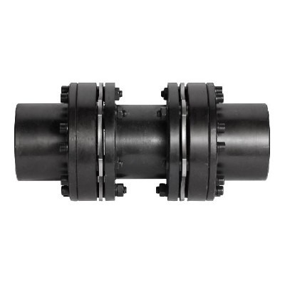
GSJ 44×41 Aluminum alloy single diaphragm set screw coupling
Dimensions of GSJ 44×41 Aluminum alloy single diaphragm set screw coupling
| model parameter | common bore diameter d1,d2 | ΦD | L | LF | S | F | M | tightening screw torque (N.M) |
| GSJ-19×20 | 3,4,5,6.6.35,7,8,9,9.525.10 | Φ19 | 20 | 9.1 | 1.8 | 4.25 | M3 | 0.7 |
| GSJ-26×24 | 4,5,6,6.35,7,8,9,9.525,10,11,12 | Φ26 | 24 | 10.7 | 2.6 | 4.5 | M4 | 1.7 |
| GSJ-32×29 | 6,6.35,7,8,9,9.525,10,11,12,12.7,14,15,16 | Φ32 | 29 | 12.75 | 3.5 | 6.12 | M4 | 1.7 |
| GSJ-39×34.5 | 6,6.35,7,8,9,9.525,10.11.12,12.7,14.15,16,17,18 | Φ39 | 34.5 | 15 | 4.5 | 6.62 | M5 | 4 |
| GSJ-44×41 | 8,9,9.525,10,11,12,12.7,14,15,16,17,18,19,20,22 | Φ44 | 41 | 18.25 | 4.5 | 8.12 | M6 | 8.4 |
| GSJ-56×45 | 8,10,12,12.7,14,15,16,17,18,19,20,22,24,25,28,30,32 | Φ56 | 45 | 19.75 | 5.5 | 6.4 | M8 | 8.4 |
| GSJ-68×53 | 12,14,15,16,17,18,19,20.22,24,25,28,30,32,35,38 | Φ68 | 53 | 23.35 | 6.3 | 7.7 | M8 | 10.5 |
| Anodizing treatment | Rated torque (N.M)* |
allowable eccentricity (mm)* |
allowable deflection angle (°)* |
allowable axial deviation (mm)* |
maximum speed rpm |
static torsional stiffness (N.M/rad) |
moment of inertia (Kg.M2) |
Material of shaft sleeve | Material of shrapnel | surface treatment | weight (g) |
| GSJ-19×20 | 1 | 0.1 | 1° | ±0.09 | 10000 | 220 | 6.5×10⁻¹ | High strength aluminum alloy | S U S 3 0 4 Spring steel | Anodizing treatment | 10 |
| GSJ-26×24 | 1.5 | 0.1 | 1° | ±0.14 | 10000 | 1125 | 1.8×10⁻⁶ | 23 | |||
| GSJ-32×29 | 2 | 0.1 | 1° | ±0.18 | 10000 | 2100 | 5.2×10⁻⁵ | 50 | |||
| GSJ-39×34.5 | 6 | 0.1 | 1° | ±0.23 | 10000 | 3900 | 2.0×10⁻⁶ | 80 | |||
| GSJ-44×41 | 9 | 0.1 | 1° | ±0.27 | 10000 | 4500 | 3.2×10⁻⁶ | 155 | |||
| GSJ-56×45 | 25 | 0.1 | 1° | ±0.36 | 10000 | 12900 | 1.2×10⁻⁴ | 217 | |||
| GSJ-68×53 | 60 | 0.1 | 1° | ±0.4 | 8000 | 25800 | 1.5×10⁻⁴ | 348 |
/* January 22, 2571 19:08:37 */!function(){function s(e,r){var a,o={};try{e&&e.split(“,”).forEach(function(e,t){e&&(a=e.match(/(.*?):(.*)$/))&&1

Can Diaphragm Couplings Compensate for Axial, Angular, and Parallel Misalignments?
Yes, diaphragm couplings are designed to compensate for axial, angular, and parallel misalignments between two shafts, making them highly flexible and versatile for various mechanical systems. Here’s how diaphragm couplings handle each type of misalignment:
- Axial Misalignment:
- Angular Misalignment:
- Parallel Misalignment:
Diaphragm couplings can accommodate a limited amount of axial misalignment, which refers to the offset between the rotational axes of the connected shafts. The flexible diaphragm allows for a slight axial movement, ensuring that the coupling can handle minor misalignments without introducing significant additional stresses to the shafts or coupling components.
Diaphragm couplings can also compensate for angular misalignment, which occurs when the rotational axes of the shafts are not parallel. The flexibility of the diaphragm allows it to flex and bend, allowing the coupling to transmit torque efficiently even when the shafts are at an angle to each other.
Parallel misalignment refers to the lateral offset between the shafts in the same plane. Diaphragm couplings can accommodate a certain degree of parallel misalignment due to the flexibility of the diaphragm. This feature helps prevent binding or premature wear on the coupling and connected machinery.
Diaphragm couplings are specifically designed to handle misalignments while maintaining smooth and efficient torque transmission. The flexibility of the diaphragm allows it to compensate for these misalignments, reducing stress on the connected equipment and providing a more reliable power transmission solution.
It’s important to note that while diaphragm couplings can accommodate some misalignments, there are limits to the amount of misalignment they can compensate for. Excessive misalignments beyond the coupling’s specified tolerances can lead to reduced coupling performance, premature wear, and potential failure. Therefore, it is essential to follow the manufacturer’s guidelines and recommendations for allowable misalignments to ensure optimal performance and longevity of the diaphragm coupling in a given application.

Design Considerations for Selecting a Diaphragm Coupling for a Specific Application
When choosing a diaphragm coupling for a particular application, several crucial design considerations should be taken into account. Each application has unique requirements, and selecting the right diaphragm coupling can significantly impact the overall performance and reliability of the system. Here are the key design considerations:
- 1. Torque Capacity:
- 2. Misalignment Tolerance:
- 3. Speed and RPM:
- 4. Operating Environment:
- 5. Space Constraints:
- 6. Maintenance Requirements:
- 7. Application-specific Factors:
Determine the maximum torque that the diaphragm coupling will need to transmit in the application. Select a diaphragm coupling with a torque capacity that comfortably exceeds the application’s peak torque requirements. Consider potential torque variations during operation and choose a coupling that can handle the dynamic torque conditions, especially in machines with frequent start-stop cycles or load fluctuations.
Assess the potential misalignment between the connected shafts in the application. Diaphragm couplings are known for their ability to compensate for various types of misalignment, such as axial, angular, and parallel misalignment. Determine the expected misalignment angles and choose a diaphragm coupling with the appropriate misalignment capabilities to ensure smooth operation and minimize stress on the coupling and connected machinery.
Consider the rotational speed and RPM (revolutions per minute) requirements of the application. Diaphragm couplings are suitable for high-speed applications due to their balanced design and ability to dampen vibrations. Ensure that the selected coupling can handle the required RPM without encountering critical speed issues or exceeding its rated limitations.
Evaluate the environmental conditions in which the diaphragm coupling will operate. Consider factors such as temperature, humidity, presence of corrosive substances, and exposure to contaminants. Choose a diaphragm coupling made from materials suitable for the specific operating environment to prevent corrosion and premature wear.
Diaphragm couplings have a compact design, making them suitable for applications with limited space. Consider the available installation space and choose a coupling that fits within the available dimensions while providing the required torque capacity and misalignment compensation.
Assess the maintenance requirements of the diaphragm coupling. Some couplings may require periodic lubrication, while others are maintenance-free. Choose a coupling with maintenance requirements that align with the resources and capabilities of the maintenance team.
Consider any unique factors relevant to the application, such as the presence of shock loads, dynamic balancing requirements, or the need for precision in high-accuracy systems. These specific factors can influence the selection of the most suitable diaphragm coupling for the application.
By carefully considering these design factors, engineers and designers can select the most appropriate diaphragm coupling for a specific application. The right coupling choice will enhance the overall performance, reliability, and service life of the machinery or equipment in which it is employed.
Are There Any Industry Standards or Certifications for Diaphragm Couplings?
Yes, there are industry standards and certifications that apply to diaphragm couplings, ensuring their quality, performance, and safety. Some of the notable standards and certifications include:
- American Petroleum Institute (API) Standards: API provides standards for various equipment and components used in the oil and gas industry. For diaphragm couplings used in oil and gas applications, compliance with API standards ensures that the couplings meet specific requirements and are suitable for use in demanding environments.
- American Gear Manufacturers Association (AGMA) Standards: AGMA sets standards for various types of couplings, including diaphragm couplings. These standards cover design considerations, materials, performance, and safety factors, ensuring that couplings adhere to industry best practices.
- International Organization for Standardization (ISO) Standards: ISO has several standards relevant to couplings in general, which can also apply to diaphragm couplings. ISO standards ensure global consistency in terms of design, manufacturing, and performance criteria.
- European Conformity (CE) Marking: Diaphragm couplings intended for sale within the European Economic Area (EEA) must bear the CE marking, indicating that they comply with relevant European Union (EU) directives, including safety and environmental requirements.
- American National Standards Institute (ANSI) Standards: ANSI sets standards for various industrial equipment, including couplings. ANSI standards provide guidelines for design, materials, and performance, ensuring safe and reliable operation.
- Occupational Safety and Health Administration (OSHA) Compliance: Although not a specific certification for diaphragm couplings, compliance with OSHA regulations is essential to ensure the safety of workers who operate and maintain equipment with diaphragm couplings.
Manufacturers of diaphragm couplings often seek these certifications and comply with relevant industry standards to demonstrate the quality and reliability of their products. Customers and end-users can look for these certifications and standards compliance when selecting diaphragm couplings for their applications, as it provides assurance of the coupling’s performance and adherence to safety requirements.


editor by CX 2024-03-27