


Hangzhou Hengli Transmission Co., Ltd.
Mechanical seal installation and precautions manual
The mechanical seal is a highly precise machine part. Its performance and life are greatly related to the operating conditions of the host, the accuracy of the host and the installation of the seal. Therefore, you must read this manual carefully before use.
XNUMX. Scope of application
This installation manual is suitable for the installation of mechanical seals for rotating shafts, the rotating speed is less than or equal to 5000 rpm or the end speed is less than or equal to 25m/s, the sealing working temperature is -40℃~220℃ or the medium temperature is lower than 400℃.Mechanical seals for other equipment can be used as reference. If you have any special requirements or details, please contact Hangzhou Hengli Transmission Co., Ltd.
Two, installation preparation
1.Verify the seal to be installed, check whether the pump position number or pump model marked on the sealed packing box is consistent with the pump to be installed, check the seal assembly drawing, and master the seal structure and installation position.
2. In accordance with the relevant disassembly sequence and requirements of the pump, remove the bearing box and other related parts of the pump, and remove the old sealing device.
3. Carry out visual inspection and dimensional inspection of the relevant parts of the sealed cavity of the pump, including the matching dimensions, space dimensions, shape and position tolerances, etc., and deal with them accordingly.
3.1 Check the axial and radial runout values of the rotating shaft in the sealed cavity relative to the stationary cavity to ensure that it does not exceed the limit values specified by the relevant national standards.
Check the shaft end, the runout is less than 0.1mm (as shown in Figure XNUMX)
Axis radial inspection, the runout is less than 0.05mm (as shown in Figure XNUMX)
Check the perpendicularity between the end face of the seal cavity and the shaft, and the allowable error is less than 0.05mm (as shown in Figure XNUMX). If the above requirements cannot be met, the relevant parts should be repaired and adjusted.


Figure XNUMX Figure XNUMX Figure XNUMX
3.2 In order to avoid damage to the non-metallic auxiliary sealing ring during installation, a 2×30° chamfer should be repaired at all shaft shoulders where the non-metallic sealing ring slips (as shown in Figure 3.2), and the sharp corners should be rounded and rounded. The trimming is smooth, the edges and corners should be trimmed at the keyway or counterbore, and the metal surface roughness Ra in contact with the stationary sealing ring (pad) should be less than XNUMXμm.

Figure XNUMX
3.3 For the first installation, check whether the connection and matching dimensions of the installed mechanical seal are consistent with the requirements of the mechanical seal assembly drawing, and whether there is interference between the internal space and the external space dimensions.
4. Clean the sealed cavity, and check again whether there are any damages or defects on the surface of each installation seal.
5. Wipe the surface of each part, and apply a proper amount of lubricant to all installation matching parts. The selected lubricant should be compatible with the auxiliary sealing rubber material and the sealed medium, such as water, soapy water, silicon grease, glycol or Glycerin etc.The ethylene propylene rubber material should not come into contact with mineral oil.
Three, mechanical seal assembly
1. Environmental requirements: The assembly of mechanical seals should be carried out in a dry and clean environment, and the workbench should be clean and free of debris.White line gloves are usually provided in the sealed packaging box, and the sealed assembly needs to wear gloves.
2. Disassemble the mechanical seal packing box, carefully take out the seal, check the model and quantity of each mechanical seal with the packing list, tear off the skin-tight packaging film with your hands or cut with a knife, and pay attention to protect the seal end surface from hard objects. In case of collision, check whether the sealing end face and other surfaces are intact.
3. Units with sealed end face aperture testing equipment can check whether the flatness of the sealed end face meets the requirements of aperture inspection.Measure the free height of the bellows assembly or spring assembly against the seal assembly drawing.
4. The installation method varies with the type of mechanical seal and the type of machine, but the installation essentials are almost the same. The installation steps and precautions are as follows:
4.1 CHB bellows series mechanical seal assembly
4.1.1 Install the sealing ring and gasket on the shaft sleeve, and tighten the screws evenly in the diagonal direction.The tightening torque of each screw should be as consistent as possible. Uneven tightening force may cause deformation of the end face of the moving ring, resulting in seal leakage.
4.1.2 Install the bellows assembly (stationary ring) and gasket on the inner side of the gland (the side close to the seal cavity), and the water jacket is inserted from the other side of the gland. The fastening screw used here is more than the moving ring Should be longer, tighten the screws evenly.
4.1.3 Be careful not to over-compress the bellows assembly during the installation process, so as not to cause the bellows to lose elasticity or damage, and be careful not to bump the end face of the sealing ring.
4.1.4 Wipe clean the end faces of the dynamic and static seal rings with alcohol. There should be no fine fibers or particles. The end faces of the dynamic and static rings are opposite. Carefully put the shaft sleeve into the water jacket in the gland. Gently bring the end faces of the moving and static rings together.
4.1.5 Install the water seal on the gland. A little lubricating oil can be applied to the inner hole of the water seal during installation.One end of the shaft sleeve must be exposed to the outside of the water seal.
4.1.6 Install the shaft sleeve transmission parts, shaft seals, gland stop pads and other parts to the corresponding positions of the seal. Some pumps use threaded transmission between the shaft sleeve and the pump shaft. You need to pay attention to the thread direction. The integrated seal needs to install the limit plate in place and fix it.
4.1.7 After the seal assembly is completed, the entire set of seals should be temporarily stored before the pump is installed.
4.2 CHT, CHW spring series mechanical seal assembly
4.2.1 Install the sealing ring and gasket on the shaft sleeve, and tighten the screws evenly in the diagonal direction.The tightening torque of each screw should be as consistent as possible. Uneven tightening force may cause deformation of the end face of the moving ring, resulting in seal leakage.
4.2.2 Install the spring assembly (static ring) and gasket on the inner side of the gland (the side close to the sealed cavity), and insert the CHW series water jacket from the other side of the gland. The fastening screws used here are more mobile The ring should be longer and tighten the screws evenly.
4.2.3 Wipe clean the end faces of the dynamic and static seal rings with alcohol. There should be no fine fibers or particles. The end faces of the dynamic and static rings are opposite. Carefully put the shaft sleeve into the water jacket in the gland. Gently bring the end faces of the moving and static rings together.
4.2.4 For CHW series, install the water seal on the sealing gland, and a little lubricating oil can be applied to the inner hole of the water seal during installation.One end of the shaft sleeve must be exposed to the outside of the water seal.
4.2.5 Install the shaft sleeve transmission parts, shaft seal, gland stop gasket and other parts to the corresponding position of the seal.
4.2.6 After the seal assembly is completed, the entire set of seals should be temporarily stored before the pump is installed.
4.3 CH5, CH45 spring series mechanical seal assembly
4.3.1 In order to reduce the friction resistance, the part where the mechanical seal is installed on the shaft should be coated with a thin layer of oil for lubrication. Taking into account the compatibility of the rubber O-ring, if it is not suitable to use oil, it can be coated with soapy water.The floating static ring has no anti-rotation pin structure, so it is not suitable to be oiled, and should be dry installed into the gland.
4.3.2 First install the static ring and gland on the shaft sleeve, taking care not to collide with the shaft, and then install the moving ring assembly.The set screws of the spring seat or transmission seat should be tightened evenly in several times.
4.3.3 Before fixing the gland, push the compensation ring by hand for axial compression. After loosening the compensation ring, the compensation ring can automatically spring back without jamming, and then evenly lock the gland bolts.
4.4 Installation of O-ring and V-ring
The installation quality of O-rings and V-rings has an important impact on their sealing performance and service life. Leakage problems are often caused by poor installation.
O-rings and V-rings are not allowed to be scratched and installed incorrectly during installation, and O-rings and V-rings are not allowed to be twisted.Before assembling, the sealing groove and the sealing coupling surface must be strictly cleaned. At the same time, lubricating oil shall be applied to the surface of O-ring and V-ring assembly.
In order to prevent O-rings and V-rings from being cut or scratched by sharp edges such as sharp corners and threads during installation, a lead-in angle of 15°-30° should be left at the shaft end and hole end of the installation.
In addition, it is necessary to prevent missing or using scrap O-rings and V-rings, and pay attention to the installation direction of the retaining ring
Four, inspection
The length of the bellows assembly of the CHB series welded metal bellows mechanical seal part specifications is long and short. Please be sure to check the seal assembly drawing and check that the actual installed bellows assembly length (free length) should be longer than the bellows assembly in the assembly drawing. The working height is 4~5mm.
Five, assembly
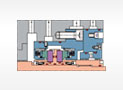
1. Due to the large differences in the structure of various types of pumps, the installation methods of mechanical seals are also very different.The mechanical seal needs to be installed according to the structural characteristics of the pump. The following describes the mechanical seal installation of typical cantilever pumps and dual-support pumps for reference only.
1.1 The shaft sleeve of the general cantilever pump is directly pressed and fixed by the impeller, and the key transmission is adopted.When installing, put the complete seal on the shaft first, install the pump cover, pay attention to the position of the flushing, quenching, and draining ports on the positive gland, and fix the sealing gland.Note that the shaft seal gasket and gland gasket should be installed in place.After fixing the pump cover to the suspension, install the key, impeller and other parts.
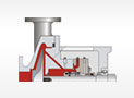
1.2 When installing the seal of the dual-support pump, sleeve the entire seal from the shaft end and push it slowly to the dense
In the sealing cavity, pay attention to the keyway of the shaft sleeve to be aligned with the key on the shaft, because the shaft sleeve of the double-support pump seal has multiple transmission modes, and the positioning of the shaft sleeve is also different, so the fixing position and fixing method of the shaft sleeve are also different. , You need to refer to the seal assembly drawing, you must ensure that the sealed bellows or spring has a proper compression amount. After the sleeve is pushed in place, pay attention to the position of the flushing, quenching, and draining ports on the gland. The gland enters the stop and matches and Press the gland gasket, fix the gland, tighten the nuts evenly, install the shaft sleeve sealing ring, and fix the shaft sleeve.
1.3 For the cartridge mechanical seal, the shaft sleeve and gland are fixed. After completing the bellows seal assembly, do not forget to remove the limit plate or fix the limit plate in a place that does not contact the rotating parts.
2. Refer to the requirements of the seal assembly drawing, connect the sealed flushing, quenching, draining pipelines and the sealing auxiliary system, the small hole in the flushing interface on the gland leads to the sealed cavity, and cannot be confused with the quenching and draining interface. In addition, Our company's bellows mechanical seal is convenient for users to install left and right or front and rear ends. Two flushing or quenching ports on the same gland are processed symmetrically, and the unused port must be sealed when used.The quench hole is usually at the top, and the cooling water enters and exits from the top.
Six, operation:
1. The air in the sealed cavity must be exhausted, especially the double-end seal with sealing liquid, and more attention should be paid to exhaust the air to avoid damage to the seal end face during dry operation.
2. The crank check should feel resistance, but it should not be heavy.
3.Open the inlet valve of the pump, introduce the medium, and observe the sealing condition under a certain static pressure.
4.Rotate the pump shaft slowly by hand to observe whether the seal is leaking.If there is a large leak, there is a problem with the installation of the seal or a problem with the sealing ring itself. The seal should be disassembled to find the cause carefully, and reinstall after troubleshooting.
5.If the condition is good, the pump can be started.For pumps with high-temperature media, the pump needs to be slowly heated as required before starting the pump, and the pump can be started after the sealed cavity reaches a suitable temperature.
6.Pay attention to the opening and closing requirements of the valves on the auxiliary system pipeline, and pay attention to whether the auxiliary system is working well.
7.In the initial stage of starting the pump, there may be slight leakage in the mechanical seal. This is normal, and the leakage will gradually decrease. If the leakage increases, it means there is an installation problem or the sealing parameters exist.
In the case of problems, you should carefully analyze the possible problems, stop the operation if necessary, and disassemble the pump to find the cause.
Seven, seal disassembly:
1.Before disassembling the mechanical seal, make sure that the pump has stopped running, and that the temperature and pressure meet the requirements for safe disassembly, close the system pipeline valve, and drain the remaining medium in the pump. Poisonous, harmful, flammable, and explosive media need to be flushed or diluted After reaching the harmless requirement.
2.When disassembling the relevant parts of the pump and the mechanical seal, the container bellows seal must first reinsert the limit plate into the limit groove and fix it, remove the shaft sleeve and the fixing on the gland, and then remove the seal as a whole. For seals of other structures, the shaft sleeve part and the gland part can be removed separately.
3.When disassembling the shaft sleeve parts, apply force on the shaft sleeve removal groove on the seal or on the non-sealed mating surface.
4.The parts that need to be reused should pay attention to protect the sealing end face and other sealing faces, and do not apply force to the end face and the vicinity of the end face.
5.For mechanical seals that have not reached the normal service life, in order to analyze the reasons for the failure of the seal, please keep the disassembled seals properly.
XNUMX. Precautions for mechanical seal installation:
1.The installation steps of the mechanical seal are closely related to the structure of the equipment used, and should be installed in accordance with the characteristics of the equipment.
2.When installing flat gaskets, it is necessary to ensure that the axial tightening force is even within the circumference.
3. In order to reduce frictional resistance, lubricating oil or grease can be evenly coated on the shaft or sleeve in contact with the seal.But it should be noted that when using ethylene-propylene rubber "O" ring, it should not come into contact with mineral oil and grease. It can be cleaned and lubricated with water or silicone oil.
4. The "O" ring of the stationary ring should be lubricated with water, and the stationary ring should be installed by applying external pressure.
5. When installing double-coated PTFE, the outer seam must be away from the installation direction.Vigorous bending of PTFE can cause failure.When installing a pure PTFE "O" ring, sufficient time and small force are required to avoid scratches, otherwise it will cause failure.
6. Do not use lubricating oil on the sealing surface. The assembly process should be carried out in a dry, dust-free and clean working environment. The sealing surface must be kept clean.
7. The mechanical seal whose spring's rotation is related to the rotation of the shaft (ie, a fixed rotation mechanical seal).From a stationary ring to a rotating ring, a clockwise rotating shaft needs a right-handed spring, otherwise it is left-handed.
8. When using a mechanical seal that is driven by a screw on a shaft (sleeve), a recessed set screw with a blade should be used to firmly fix the rotating part on the shaft (for special requirements, please refer to the seal installation general Figure).
9. Flexible graphite is used as an auxiliary seal. It should be tightened in order by axial bolts in a dry state (not cross-tightened in the circumferential direction) to make the flexible graphite fully deformed twice.
10. When installing a stationary ring with a flexible graphite sealing ring, it should be fully compressed (if a bench drill is used), and the perpendicularity between the working surface and the axis should not be greater than 0.1mm.
11. During the assembly process, the seal cannot be knocked. After the seal is assembled, it is not allowed to knock or hit the shaft, shaft sleeve, sealing end cover, etc. to avoid damage to the seal ring.
※Pay attention to the following conditions during the sealing operation to ensure the service life of the seal:
Avoid medium pressure fluctuations;
Avoid frequent driving and parking;
Avoid pump evacuation, cavitation, etc.;
Avoid interruption of flushing fluid and quench water; regularly check whether the sealing auxiliary system is working properly;
Avoid using hard water, quench water;
